Tuesday 4 March 2014

Pull Wire Pulleys

Only one of the Pull Wires is able to achieve a straight drop down through the Clock Room to the Ringing Room, that's the 3rd.  The other seven Pull Wires have to be diverted at some point between bell frame and Repeater Bell.  Various designs of pulleys have been utilised for the diversions depending if they are floor or ceiling mounted.  So far I've found some routes changed in the Belfry, on top of the lead flooring, some on the Clock Room ceiling others on the Clock Room floor.  I've taken some pictures of a couple taken from the 6th's route on the Clock Room ceiling.


 Both the pulleys have cast iron frames and sheaves, the one with the single screw has survived best of the two, the sheave still revolves.  The other had two screws fixing it to the ceiling, both screws had been the centre for corrosion so the cast frame is beyond repair.

The pulley pictured above will be stripped down and refurbished.  I don't think we'll use it for the new set up as we need to minimise the friction in the Pull Wire routes.  This is one of those decisions regarding accurate restoration of original installation or sympathetic improvement where we can to aid efficiency.

Thursday 27 February 2014

Headstock to Frame Clearance

Due to my discovery that some of the Stay Socket Brackets from Seage's Silent Ringing Apparatus could have the same hole centres, I needed to carry out a survey.


The table above shows the Hole Centre's on the Headstocks and the clearance between the outside edge of the Stay Socket and the Bell Frame.  Seage's Stay Socket Brackets have to fit within the clearance or they will clash with the frame as the bell rotates.  Looking at the 4th, we only have 1" clearance; so that explains the countersunk heads on the fasteners for that bracket.  Bracket thickness is 11/32nd of an inch; working in imperial fractions to stay with the Victorian era, the hex head bolts have larger head depths than is now normal so they would have clashed.  Other brackets are 1/2" thick.
If I sort the brackets in size of Joggle, smallest first, they will fit the bells in the following order;
 
4, 1, 3, 8, 6, 7, 5, 2
 
The Seage's Bell Frame Casting is in the same position, relative to the Stay Side Bearing, on every bell; therefore the bigger the clearance the more joggle is required to engage with the Cowhorns.
 
I don't understand, yet, why the 8th has the second smallest hole centre size?


Wednesday 26 February 2014

Stay Socket Bracket In Place

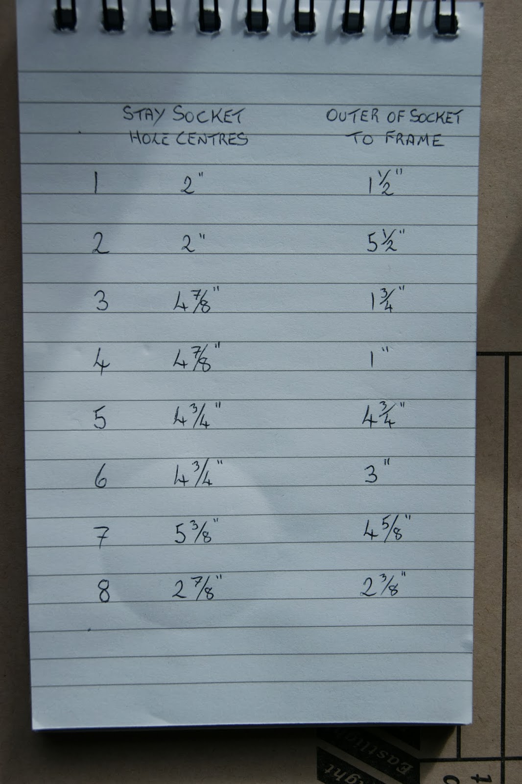
The Bracket I found in my 'Fantastic Find' is the only one of the eight with countersunk fasteners being used to fix it to the Headstock.  When I first found the seven brackets, which have varying amounts of offset or 'Joggle' away from the Stay Socket, I thought the smaller bells would have less joggle and the larger more joggle.  I had noticed that the hole centres for the fasteners appeared to be unique to each one, that would make them fool proof, as each would only fit its own headstock.  Offering up the latest find to see where it fitted, it went on the 3rd so that's where I assumed it belonged.

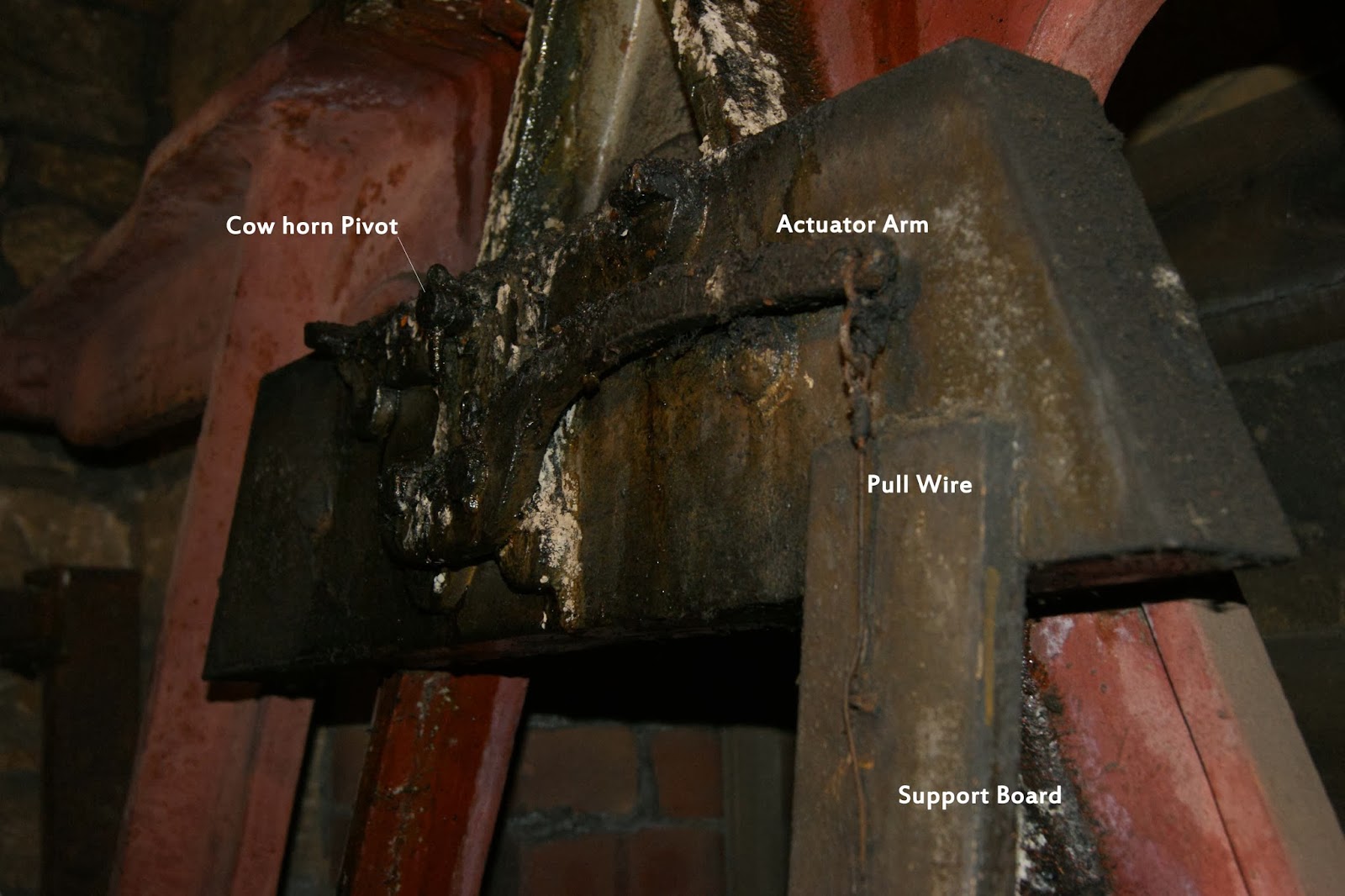
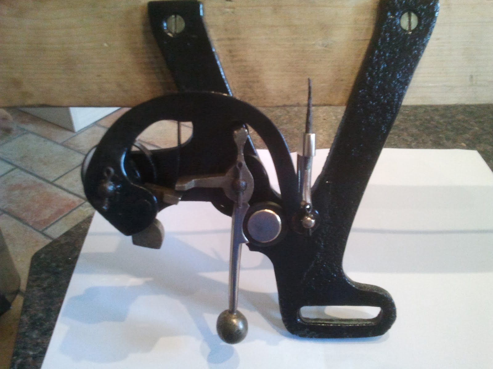
 The Bracket shown loosely fixed in position.  When the bell is Up the bracket will interface with the Cow Horn above the Stay Track, ie it will be pointing 180 deg the other way.

A slightly different view showing how close the Bracket comes to the Gudgeon (shaft which rotates in the bearing)  Also just in shot, the top of the Plain Bearing housing.
When I got the Bracket home and started to clean it ready for painting, I found four dimples on the face; it belonged to the 4th not the 3rd!  Just shows, one should never assume.  I'll need to do more investigation now as two Headstocks have the same fastener centres, therefore not drilled to make them failsafe when fitted.

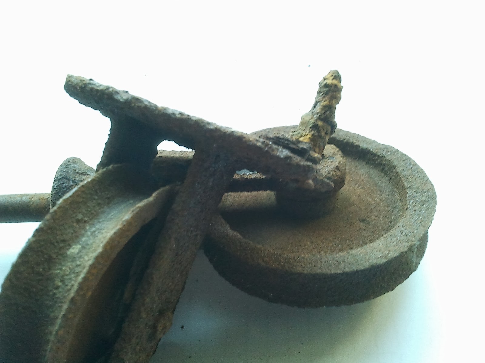
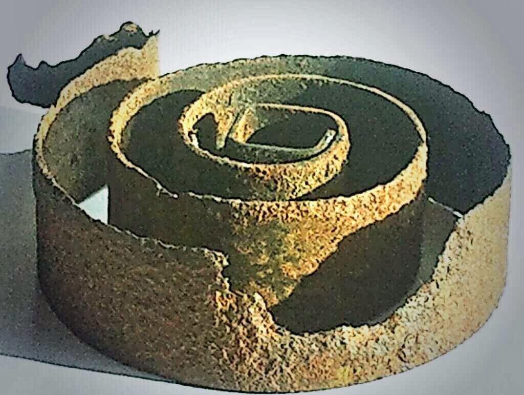
The semi-cleaned bracket showing the very slight amount of Joggle.  This item is Wrought I think.  The end has been worked in a Blacksmith's Forge, heated up then hammered to Upset and thicken the end, followed by forming of the finished Joggle to interface with the Cowhorn.

Monday 17 February 2014

Belfry Pull Wire Run

Up in the Belfry; the 'room' where the Bells are mounted just under the Tower roof, rather than the whole tower, the Seage's Silent Ringing Apparatus is made up of the Frame Mounted equipment and a Pull Wire.  Most of the Pull Wire side of the Seage's has been removed, rotted away or been damaged over the years.  The 7th Bell has the most intact equipment left in place.  The Bell Frame was mounted above the original roof of the Church Tower, the tower was extended in the 1890's when the Belfry was installed, being paid for from public subscription.  Seage's Pull Wires and ropes come through the lead covering of the original roof.

Bottom of Support Board
The top end of the Pull Wire connects to the Actuator Arm, described in a previous post, below is a photo of the equipment mounted to the Bell Frame underneath the 7th bell.

Seage's on the 7th
The photo shows the As Found state of the equipment.  There is little or no corrosion of the metal parts here as they have been coated in castor oil which was used to lubricate the plain bearings on the Head Stock for many years.  A strip down and clean is all that is required, followed by a new Stainless Steel Pull Cable fitting.  The function of the Support Board is one of damage prevention, if the Pull Wire were to be kicked or caught during routine maintenance of the bells the Timing of the Repeater Bell would be thrown out.

Tuesday 11 February 2014

Fantastic Find

Today I went to the Tower to try and find the routing for each of the Pull Wires leading from the Belfry.  I did make more headway with that task, but the find of the day was a tin box, some spanners, a hammer and a piece of steel.
A shelf full of Clutter

The shelf is very rarely seen as it is hidden by the Belfry door when it is open.  Today it was still light when I was up there and I just noticed the old tin box, these can be collectable if they have writing on them, would have helped for Tower Funds.

Fasteners and Washers
The find was worth more than an old tin box for the Seage's Silent Ringing Apparatus project.  Some weeks ago I located most of the Stay Socket Brackets in the Clock Room, one was missing which I thought was odd; why save seven in one place but not a complete set?  None of the fasteners used to fix the brackets were found at that time.  Bingo; today the lost bracket and fasteners are here.  The remaining bracket was resting on the tin box, see top picture.

Missing Bracket on left

Fasteners, Washers and The Bracket

Thursday 6 February 2014

Corrosion Hits Springs

I'm not sure how the first four Repeater Bell mechanisms I removed just happened to need no more than a good clean up and painting, just luck.  The remaining four, being those for the 1st, 2nd, 6th and 8th; were in a lot worse condition.  Two Trigger castings are badly corroded at the weakest point where the brass cable pivot attaches.  Four of the return springs are either broken or corroded badly enough to need replacing.

Clapper return spring
The worst of the corrosion has been assisted by good old disimilar metals syndrome, or Galvanic Corrosion.  The hook at top left is hooked over the Clapper which is made from Brass.  The semi-circular hole has been caused by touching the Brass pillar where the Rubber Bump stop is fitted.

I'm now on the trail of a company that will manufacture some new Clock Springs, the technical term for springs of this shape and function.

Monday 27 January 2014

Repeater Bell - During Refurbishment

I thought I'd show you what the the Repeater Bell mechanism is made up of, what components are used and what material they're made from.

Plan view of the 6 components

Side on view


The main item is the Y Frame, a cast iron part with 3 pillars rivetted to the frame; 2 of the pillars are mild steel the other one is brass.  The large brass spigot is there to act as a bump stop to restrict the travel of both the Clapper and Trigger Casting. The 2 steel pillars are dual purpose spring locators and pivot points for Trigger Casting and Clapper.  The springs slide over the pivot and fit on the lower square section followed by Trigger Casting or Clapper, these are fixed by split pin.  The last item is a brass Cable Interface, this pivots on the end of the Trigger Casting whilst being pulled up by the cable coming from the belfry.

Assembled Repeater Bell Mechanism
The fully assembled mechanism (without Bell)  There's a rubber ring fitted to the Brass Stop, I'm not sure if rubber would have been used on the original but this appears to work fine so far.  The rubber is dual purpose in that it stops metal to metal contact of both Clapper and Trigger and acts as a spacer to restrict the travel of those parts, allowing the systems to re-arm faster after striking.